Menu
MPFM
Faceplate adjustable|Wide variety|Portable ‘on-site’
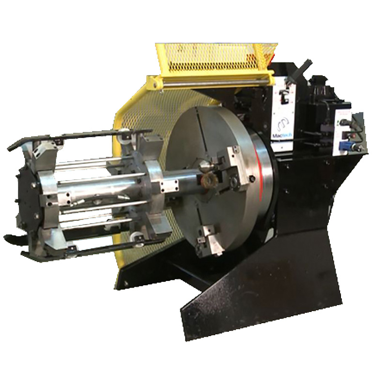
The Mactech Pipeline Machine has been designed as a portable ‘on-site’ tool for producing weld prep profiles on pipe ends.
Multiple ‘radial’ type tool holders are mounted on the rotating faceplate each capable of housing two, one inch square section tool , hanks in ‘piggy back’ fashion.
By arranging tools of different approach angles, a very wide variety of weld prep profiles can be produced.
All machine motions are derived from one common hydraulic supply source and controlled by a series of stack mounted, cam operated, tapered spool valves.
Technical Data
H1 6 – 14 4.75”ID – 14”OD Up to 1.2”, H2 12 – 24 10.75”ID – 24”OD Up to 2”, H3 24 – 36 22”ID – 36”OD Up to 2”, H4 36 – 48 34”ID – 48”OD Up to 2”, H5 48 – 60 46”ID – 60”OD Up to 2”
Clamping Unit
The clamping unit assembly consists of a double acting cylinder attached to two end caps, each machined to house seven radially positioned clamp plungers. Both end caps are securely bolted together, separated by the clamping cylinder assembly, thereby forming a self contained unit which can be easily removed from the rear of the machine for maintenance, replacement or transportation.Three sets of guide wheels are carried in fabricated skid brackets, mounted on the end caps and allow the units to be rolled into the pipe bore with the minimum of effort. These can be adjusted to suit the pipe diameter by adding the relevant spacer required.The clamp system has a unique ‘clamp cage’ concept that allows the machine to cover the range from 10 inch ID to 24 inch OD. The standard mandrel allows the machine to operate from 10 inch ID to 16 inch OD and then with the additional ‘clamp cage’ the machine can cover the sizes from 16 inch to 24 inch OD.
Faceplate
The machine faceplate is manufactured from a high strength spheroidal graphite iron casting, amply ribbed to provide maximum stiffness for the tool holder assemblies. The main drive gear is secured directly to the rear surface of the faceplate, and by virtue of it being an internal gear, provides its own protection against damage, and also protects the drive pinion mechanism.Lubricating oil for all the transmission gearing is housed within a reservoir at the rear of the faceplate.The entire faceplate assembly is supported by a pair of opposed taper roller bearings which in turn are carried on a non rotating sleeve.
Mandrel Assembly
The machine mandrel, around which the cutter faceplate rotates and slides axially, is manufactured from heat treated alloy steel with the sliding surfaces hard chrome plated and accurately ground. A flanged connection is provided between the mandrel and clamp units through which the hydraulic clamp supply lines pass via ‘0’ ring sealed joints. The main drive gearbox is securely anchored to the tail end of the mandrel to provide a rigid reaction point for the cutting forces.
Carrie Assembly
This is a fabricated steel structure, rigidly attached to the mandrel assembly and supports the feed control cylinders, the hydraulic control valves, the protective guard rail and also forms the main lifting arm. Axial feed forces are generated by two identical double acting hydraulic cylinders, symmetrically arranged about the mandrel centre. Infinitely variable feeds are achieved by controlling the flow of oil to these cylinders using a fine pressure compensated feed control valve. A single stack of lever operated; mobile type hydraulic valves are used to control all machine functions. Our unique ‘patented single lever control system’ operates all machine functions: faceplate stop/start, mandrel clamp/release, faceplate fast traverse left/right and finally, faceplate feed left/right. The effect of high impulse loads generated by sudden valve actuation are reduced by the pressure compensated tapered spool configuration of valves and the use of open centre spools in the motor control circuit. The faceplate can be jogged with the guard retracted to assist tool inspection and setting. Mandrel clamping is controlled by a block centred valve incorporating a check valve in the clamp feed line. In the event of a failure in the hydraulic supply lines, the machine will maintain its clamping effort on the tube thereby allowing the machine to come to a safe stop. All hydraulic connections to the machine are made via Aero quip FD Series 45 quick release couplings, and consist of one pressure, one tank return port
Toolbox
Identical radial type toolboxes are fastened to the faceplate in positions to suit the tube sizes being worked. Each toolbox pivots about a pair of anti-friction bearings, under the action of an eccentrically mounted guide roller. The whole assembly is given a spring bias, radially outwards by a spring mounted on the inner surface of the tool holder with an ultimate position dead stop provided within each box to absorb the axial cutting forces. This pad bears against a hardened steel sub plate located on the faceplate.Sufficient tool space for two one inch square tools having index able carbide inserts is provided in each toolbox. The toolboxes are self-contained, modular units, attached to the faceplate by a single bolt. The complete toolbox can be removed, and a replacement fitted in seconds. Toolbox location is by a positional feed screw which prevents any radial displacement of the toolbox assembly and provides a positive location in any position.
